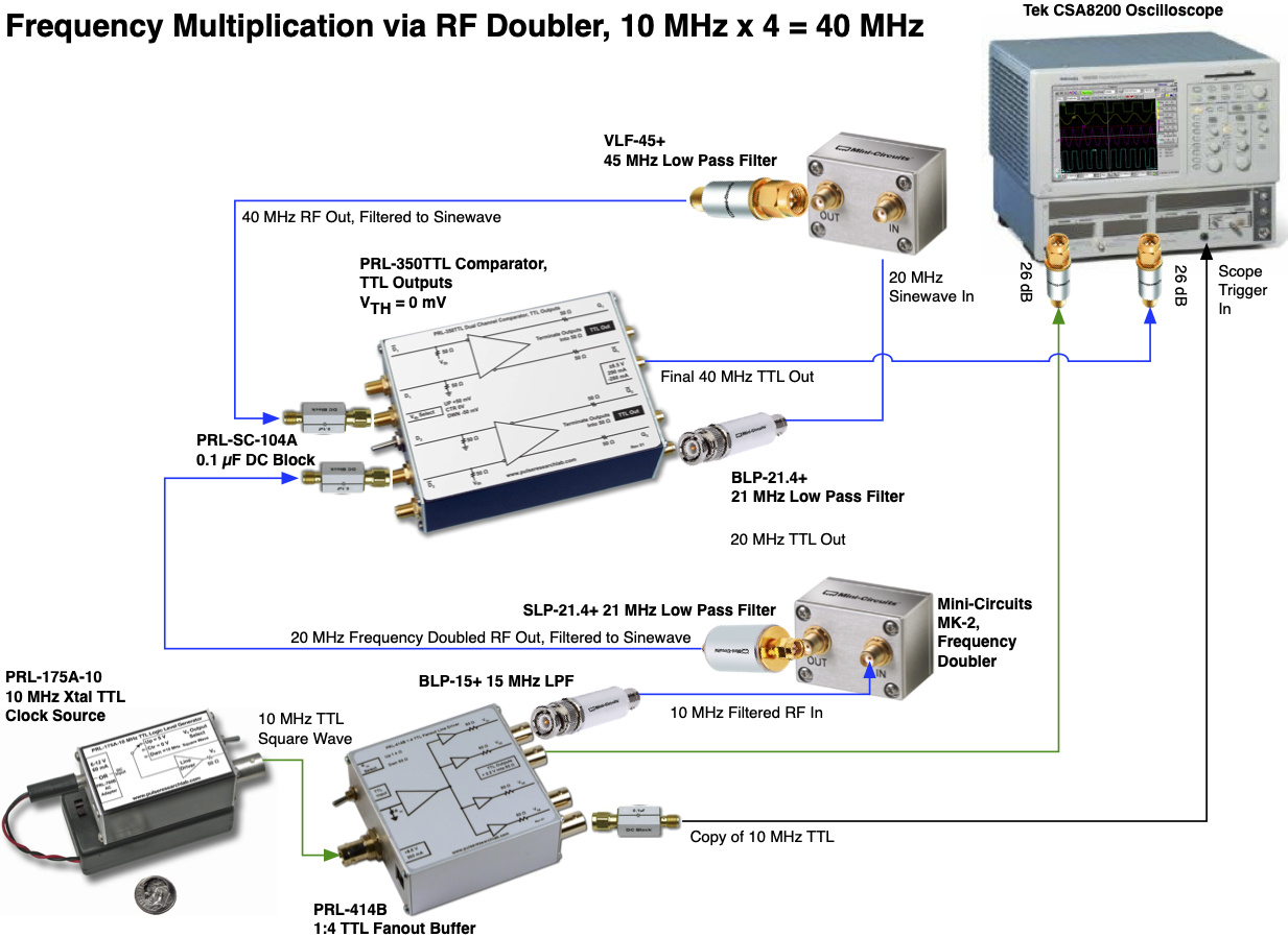
Long question, but potentially interesting. I'm experimenting with creating a 40 MHz TTL clock signal from a 10 MHz TTL source, using a set of filters and frequency doubler modules from Mini-Circuits, along with a sinewave-to-squarewave converter (basically a comparator), as follows:
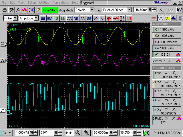
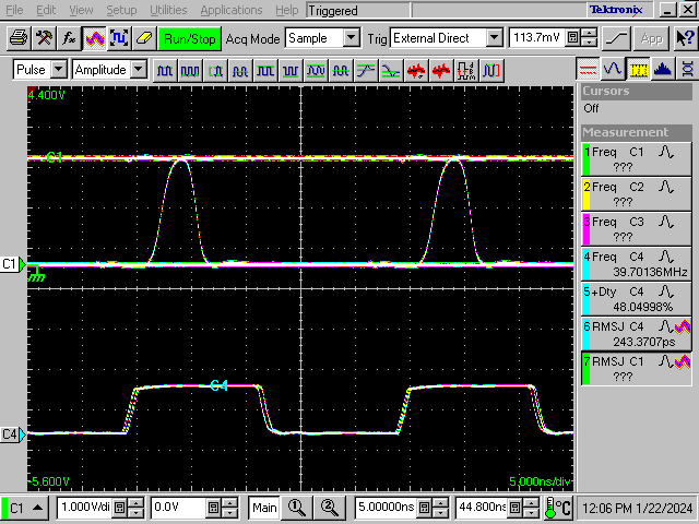
The result is 4 output pulses (blue) per input pulse (green), with an average frequency of 40 MHz, shown here when my CSA8200 is triggered on a copy of the 10 MHz signal:
but there's a distinct repeating pattern of A, B, C, and D output pulse per input pulse:
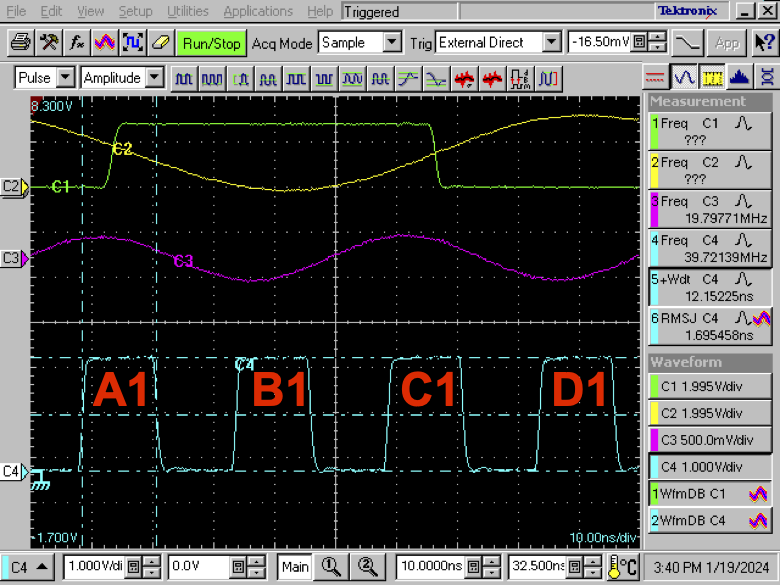
The width of A1 is slightly different from the width of B1, C1, and D1, but the same as the width of A2 (following D1).
The period from A1↑ to B1↑ is slightly different from the period from B1↑ to C1↑, but the same as from A2↑ to B2↑.
This is completely as expected from this setup, as the frequency multiplication modules are passive. The filters are to convert the square waves to sine wave before going into the multipliers, and to clean up the doubled frequencies so the converter can create closer to a 50% duty cycle when converting back to square wave. The middle stage of square wave conversion is required to get enough energy for the 2nd frequency doubler.
Since each set of edges from pulses A-D, rising or falling, is generated by a single green clock cycle, the jitter measured on A-D when triggered on 10 MHz is pretty good, typically < 10 ps RMS, regardless of which 40 MHz edge I measure or which 10 MHz edge I trigger on:
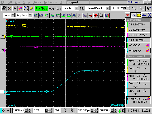
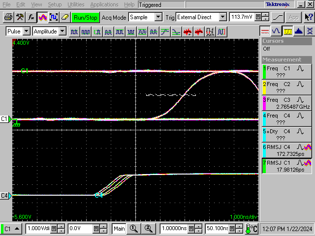
What I don't understand is what I see when I reverse the trigger relationship, and trigger on a copy of the 40 MHz signal, as follows:

If I display the 10 MHz and 40 MHz signals with a waveform database I see a sort of eye, but whereas I would have expected to see a lot of jitter on those 10 MHz edges, due to the edge jitter on the 40 MHz trigger, instead I see a clean 10 MHz edge:
The 40 MHz signal has 4 distinct sets of edges:
Why don't the rising edges line up if I'm triggering on the rising edge of its duplicate, or why don't the falling edges line up if I'm triggering on the falling edge of its duplicate? When I zoom in on that 10 MHz edge, I get <11 ps RMS jitter:
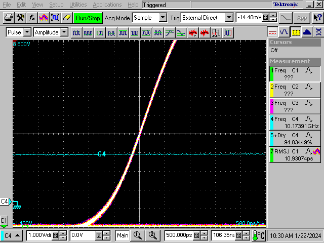
Am I missing something really obvious? Why aren't my 10 MHz edges jittering with respect to my 40 MHz trigger?
The trigger setup in all cases is External Direct with no prescalar, set to 50% level.

